Etching
The plates, or electrodes, are made of high purity, thin aluminum foil (0.05 to 0.1 mm thick). To get the maximum capacitance for a given electrode surface area, an electrochemical process called “etching” is used to dissolve metal and increase the surface area of the foil in the form of a dense network of microscopic channels.
The etching process consists of continuously running aluminum foil through a chloride solution with an AC, DC or AC/DC voltage applied between the etch solution and aluminum foil. The increase in surface area is referred to as foil gain and can be increased as much as 100 times for foil being used in low voltage capacitor applications and 20 to 25 times for higher voltage applications. (See examples of electron micrographs.)
Formation
The dielectric of the aluminum electrolytic capacitor is composed of a thin layer of aluminum oxide (Al2O3) which develops or “forms” on the surface of the etched aluminum foil during a process called “formation.”
This process of forming the dielectric oxide on the aluminum foil (electrode) requires a continuous application of DC voltage at 140% to 200% of the rated voltage for the capacitor being manufactured. The dielectric thickness of this aluminum oxide film is approximately 15Å/volt. The insulation strength is approximately 107V/cm.
Electron Micrographs of Etched Aluminum Foil
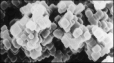
AC Etched Aluminum Foil for Low Voltage
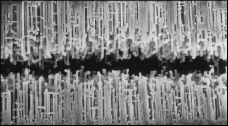
Cross Section of DC Etched High Cubicity Aluminum Foil
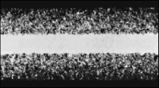
Cross Section of AC Etched Aluminum Foil for Low Voltage
Since capacitance is inversely proportional to the dielectric thickness and the dielectric thickness is proportional to the forming voltage, the relationship between capacitance and forming voltage should be:
C (capacitance) X V (forming voltage) = constant
This is true for high voltage foil which has a relatively coarse etch structure. However, for foils that have ex-tremely fine etch structures, the conversion of aluminum to aluminum oxide has a significant smoothing effect on the etch structure resulting in a non-linear relationship.
Slitting
The etched and formed foil is then slit into various widths depending on the specific size of the capacitor.
Winding
A typical capacitor winding (or element) is shown below.
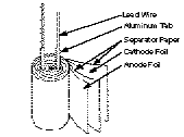
Capacitor Element
Each capacitor contains two foils, the positive foil is called the anode and the negative is called the cathode.
The anode and cathode foils, along with a separator paper called the “separator,” are rolled into a cylinder. The separator paper prevents the anode and cathode foils from coming into contact with each other and shorting.
As part of a highly automated winding process, aluminum tabs are attached to the anode and cathode foils. This completed assembly of etched and formed foil, separator paper and attached tabs is called the capacitor “element.”
Impregnation
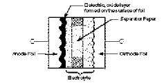
Element Cross-Section
Electrolyte is now added to the assembly by a process called “impregnation.” The method of impregnation requires the wound element to be immersed into the electrolyte by either a vacuum/pressure cycle with or without applied heat or simple absorption. The electrolyte contains a solvent such as ethylene glycol and a solute such as ammonium borate.
Should the dielectric film be damaged, the presence of the electrolyte will allow the capacitor to heal itself by forming more oxide. By selecting different electrolytes, we can improve the capacitor characteristics such as operating temperature range, frequency response, shelf life and load life.
Sealing
The impregnated element is then sealed in an aluminum can. The sealing material may be rubber, rubber backed phenolic, molded phenolic resin or polyphylenesulfide (PPS).
Aging
The final process is “aging,” during which a voltage greater than the rated voltage of the capacitor is applied at elevated temperatures. The purpose is to reform (or repair) any oxide film which may have been damaged during the slitting, winding and assembly processes.
Production Inspection
After aging, capacitors are 100% tested. All electrical requirements are checked using highly advanced automated test equipment and any rejects are removed. The capacitors are also visually inspected, and only capacitors passing both tests are accepted for packaging.
Final Inspection
The last operation before actual shipment is a final inspection by the quality department using MIL-STD-105D or its equivalent.
